Continuous Lateral Brace
A continuous lateral brace, often called a continuous lateral restraint (CLR), acts as a stiffener to a web or chord member in compression and is attached in the field by the truss installation crew. The Truss Design Drawing will denote which webs require a field applied CLR with a rectangle with an “X” through it or a rectangle that is fully blackened. The notation is added either midway on the web if only one is required or at thirds on the web member if two CLRs are required.
CLRs are used as an economical alternative to increasing web or chord member size and/or increasing lumber species or grades to more expensive alternatives. In some instances, the truss design software will not allow a particular web configuration without the use of one or two CLRs.
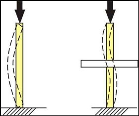
The purpose of a CLR is to prevent deformation and/or buckling of the web member and the series of truss members to which it is attached. Think of pushing down on a yardstick from the top. It bows to one side or another. When it is held, or restrained, at the midpoint it requires much more force to achieve any bending in the yardstick. This is the function a CLR plays on a chord or web member. Testing has shown when extreme loads are placed on a truss, it will begin to buckle out of the vertical (plumb) plane in which it is oriented, almost in an “S” shape. CLRs help transfer these extreme loads to adjacent trusses to prevent a truss failure.
Alternatives to a CLR exist for cases where a CLR simply won’t work. For example, if a series of trusses in consecutive layout have differing web configurations, applying a CLR can be difficult. In this instance a T-brace can be used, which is a similar sized member applied perpendicular to a web (like a “T”) for the length of the web using the same species and grade as the web member. Similarly, an L-brace can be applied in the same manner as a T-brace in instances where the T-brace may penetrate a ceiling or wall plane. Examples of this are gable end trusses, or trusses adjacent to a series of scissors trusses. Refer to BCSI for additional alternatives to CLRs and proper installation of all methods of reinforcement.
Truss installers will sometimes ask what bracing is required when setting trusses, referring to the CLRs from the Truss Design Drawings (TDD). While the CLRs are specifically called out on the TDDs, they are not the only bracing required for proper truss installation. Temporary and permanent bracing are both required during and after installation. In fact, CLRs require additional bracing to effectively do their job. Please refer to BCSI as a reference for all required bracing during and after truss installation, including bracing of CLRs. If you have any questions on required CLRs for a specific truss application, please refer to the project truss technician or salesperson.